


Hi ,

We have SEGGER J-TRACEpro for CORTEX-M processors . shop-us.segger.com/product/j-trace-pro-cortex-m-8-18-00/
We want to take the Code Coverage report . We are using Ozone IDE and loading the .OUT file to the OZONE IDE .
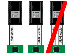
There are 2 cables that are connected to the J-TRACE pro one with normal Segger connector 20 pins that also comes with Segger J-LINK the image is shown below for this cable , this is what I am connecting to the custom board .
I know this does not carry the TRACE signals .
To get the J-TRACE Pro working there is cable shown above This connector is a 19-pin connector (0.05" / 1.27mm). It connects to the target via an 1-1 cable. the connector width is smaller compared to the J-Link Connector cable shown below .
I need documentation for STM32F051 which pins should be connected to the TRACECLK , 4 of TRACEDATA pins of the SEGGER J-TRACE Pro
wiki.segger.com/UM08001_J-Link…2FSWD_and_Trace_connector
14 TRACEDATA[0] Input Input Trace data pin 0.
16 TRACEDATA[1] Input Input Trace data pin 1.
18 TRACEDATA[2] Input Input Trace data pin 2.
20 TRACEDATA[3] Input Input Trace data pin 3.
To get the J-TRACE Pro working there is cable shown above the connector width is smaller compared to the J-Link Connector cable shown below . How do we connect the above shown cable to the MCU STM32F051 micro-controller . Is there any documentation for the STM32F051 code coverage report generation using OZONE and J-Trace PRO ? .
Thanks and best wishes,

We have SEGGER J-TRACEpro for CORTEX-M processors . shop-us.segger.com/product/j-trace-pro-cortex-m-8-18-00/
We want to take the Code Coverage report . We are using Ozone IDE and loading the .OUT file to the OZONE IDE .
There are 2 cables that are connected to the J-TRACE pro one with normal Segger connector 20 pins that also comes with Segger J-LINK the image is shown below for this cable , this is what I am connecting to the custom board .
I know this does not carry the TRACE signals .
To get the J-TRACE Pro working there is cable shown above This connector is a 19-pin connector (0.05" / 1.27mm). It connects to the target via an 1-1 cable. the connector width is smaller compared to the J-Link Connector cable shown below .
I need documentation for STM32F051 which pins should be connected to the TRACECLK , 4 of TRACEDATA pins of the SEGGER J-TRACE Pro
wiki.segger.com/UM08001_J-Link…2FSWD_and_Trace_connector
14 TRACEDATA[0] Input Input Trace data pin 0.
16 TRACEDATA[1] Input Input Trace data pin 1.
18 TRACEDATA[2] Input Input Trace data pin 2.
20 TRACEDATA[3] Input Input Trace data pin 3.
To get the J-TRACE Pro working there is cable shown above the connector width is smaller compared to the J-Link Connector cable shown below . How do we connect the above shown cable to the MCU STM32F051 micro-controller . Is there any documentation for the STM32F051 code coverage report generation using OZONE and J-Trace PRO ? .
Thanks and best wishes,
The post was edited 2 times, last by kalvacherla ().